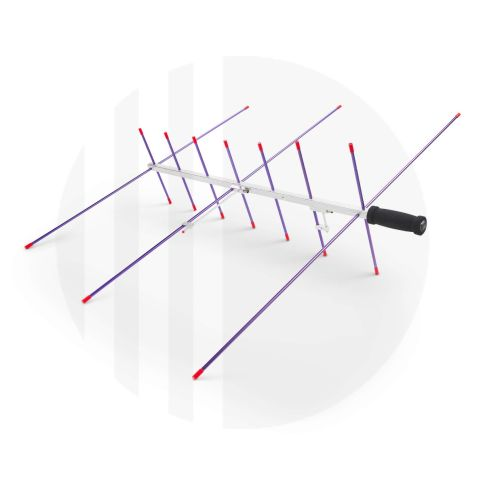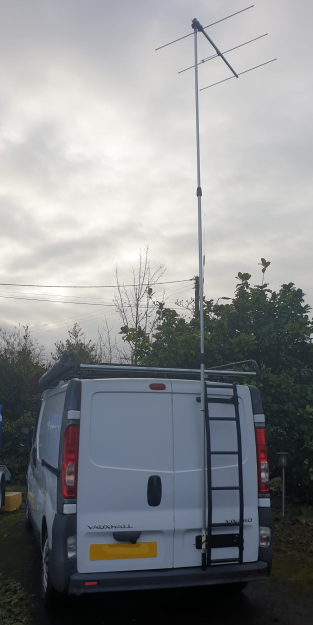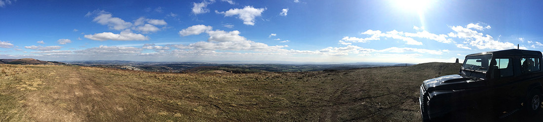
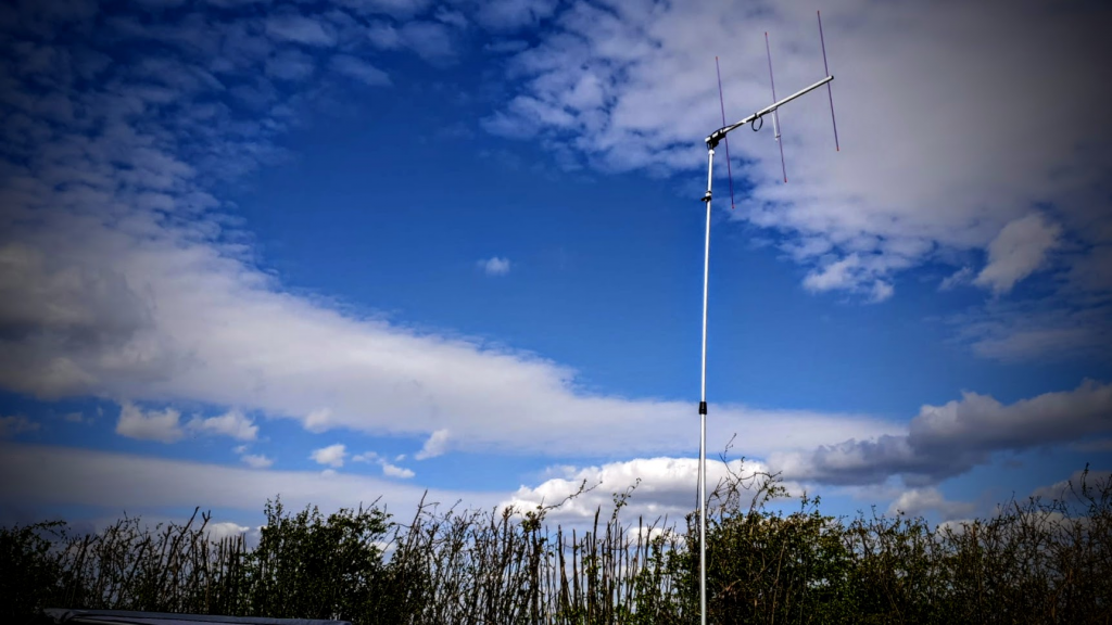
Recently I spent the weekend at Merediths Farm and Campsite in Llancloudy, a lovely quiet campsite. I set up a 2m 3-element beam (arrow) at 5m on top of a painters pole and pointed it due south. It was a test run to see if I could operate through GB3WR, over 40 miles away due south.
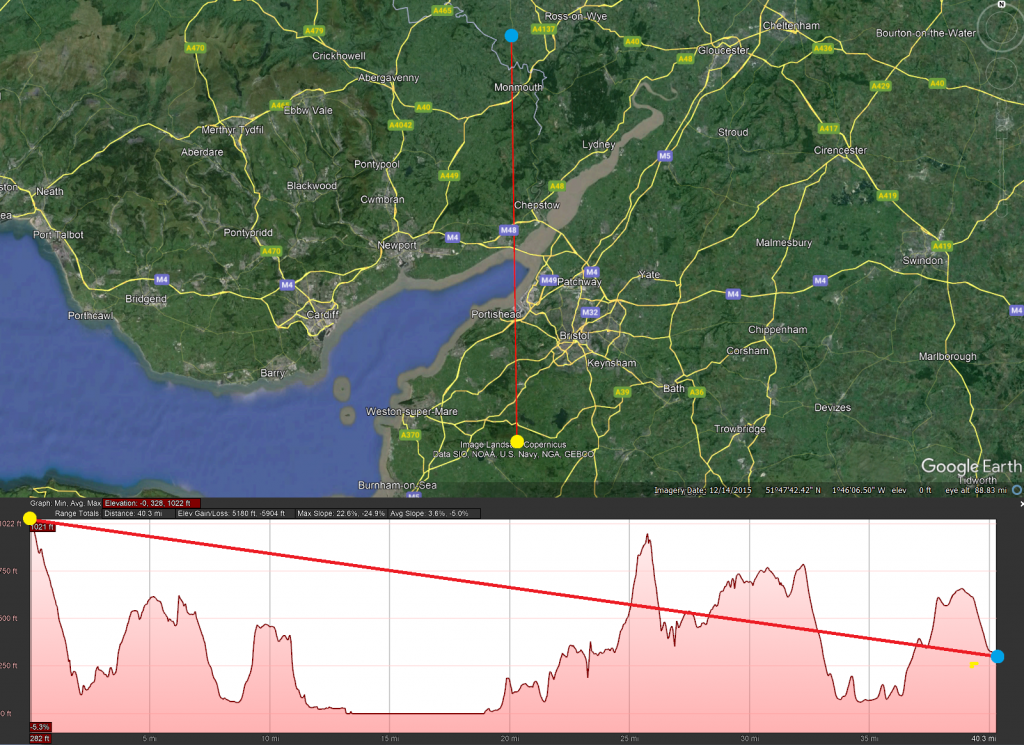
The height profile implies that it should not be possible. GB3WR is the yellow blob in the map above, my location the blue blob in Llancloudy. Amazingly I could open up the repeater with just 10w from the IC-705, so I put a couple of calls through it and made some contacts !!
G1WOV was the first, but I had attenuated WR too much when direction finding and missed his replies unfortunately. I then had contacts with M0HWP Jeremy, and M7AJO/M Callum. Dale, 2W0ODS then called in and we had a good chat, Llancloudy, through GW3WR, and into Barry, great stuff.
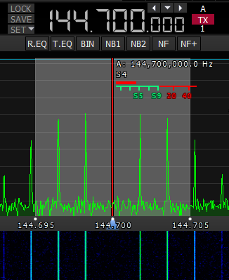
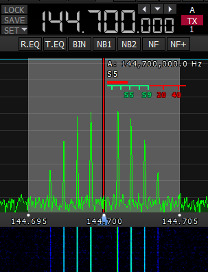
The repeater was about S5 on the IC-705 meter, I was running 10w into the 3 ele beam.
Cheers for the contacts which made it resounding success.
73