
With the new/recent Ofcom amateur radio licence changes, we are permitted to hold only one personal callsign. To that end I have released my Foundation MW6LGA callsign, and my Intermediate 2W0LGE callsign.
General
Portable Beam
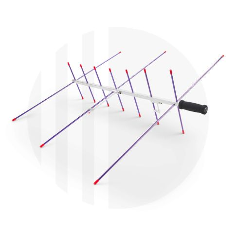
So I picked up one of the ARROW II 146/437-10BP portable 2m/70cm beams for some satellite and portable/mobile activity. Three elements on 2m, seven on 70cm.
I decided that I also wanted it on top of a 5m painters pole for easy setup when I am out in the van so I picked up an adaptor from Amazon. It was a bit pricey but it did the job and seems very strong.
I cut up some box section cable trunking I had and mounted to the top of the adaptor with a few screws and washers. I pre-drilled the adaptor plastic.
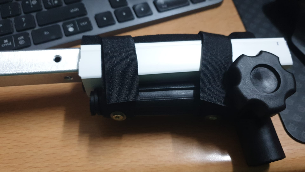
A small cut out to take the curved section on the adaptor can be seen below. It lets the box section sit flat.
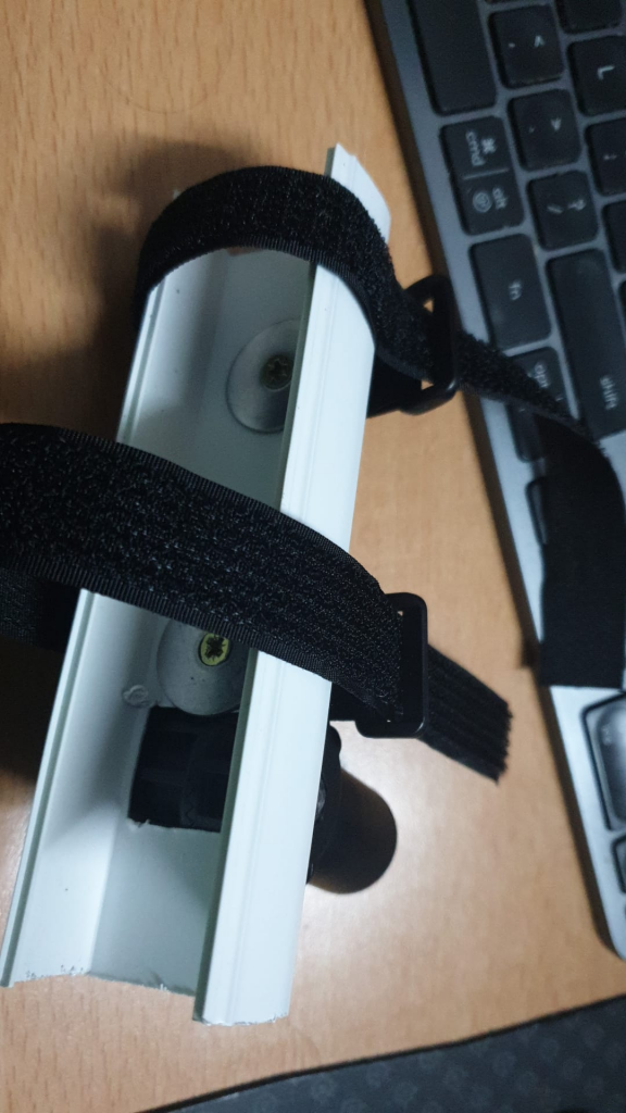
I put together some velcro straps and screwed them into the adaptor with washers. The foam/sponge grip of the antenna sits snugly in the box section and can then be velcroed in place.
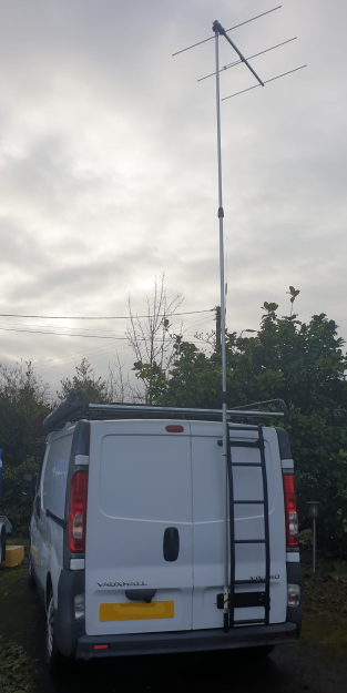
A quick test setup on the van on the top of a 5m painters pole. I am looking forward to using it when next out and about.
73 !
MB7TR – SSTV Repeater in Magor
UPDATE: MB7TR is now also closed down. There was not enough activity in the area to make it worth while.
Peter (MW0RPB) closed down the MB7TR 2m repeater in Cwmbran a year or so ago. I decided to start my own here in Magor. This time however, it would be on 70cm, using the same callsign.
MB7TR is now a 70cm, FM, regenerative sstv repeater based in Magor, S.Wales. It shares the Diamond X300n antenna with APRS station MB7UNE.
All details can be found HERE.
FM deviation using Bessel Zero method
I decided to try to work out the peak deviations in FM when transmitting from an IC-9700 and an IC-705 into a dummy load. The receiving transceiver is a SunSDR2 Pro without antenna connected. I used a software sig gen to feed both Icom radios with an audio tone via their USB audio interface.
This tone is adjusted whilst observing the FM transmission on another SDR receiver, or listening to the fundamental frequency with narrow CW filter. The injected tone’s frequency is adjusted to bring the main carrier frequency to the zero point (null) in the bessel function, the carrier at the fundamental will drop to zero on the sdr, and it will go silent on the receiver that is listening in CW mode.
Bessel Function
- 1st fundamental crossing = 2.4048 modulation index
- Deviation = 2.4048 * AF (where AF is the audio frequency applied that results in a null carrier at fundamental RF frequency)
- Bandwidth = 2 * (max audio freq + peak deviation)
- Assume 3k peak audio frequency for voice used in bandwidth calculations
IC-9700
1830 Hz FIL1 = ±4.4 kHz dev
913 Hz FIL2 = ±2.195 kHz dev
FIL1 BW : 14.8kHz
FIL2 BW : 10.39kHz
IC-705
1762 Hz FIL1 = ±4.24 kHz dev
889 Hz FIL2 = ±2.13 kHz dev
FIL1 BW : 14.48kHz
FIL2 BW: 10.26kHz
Icom Remote Utility Issue and Hamlib
When running JTDX (version rc155 with the ic-705 supported) and the Icom Remote Utility I kept getting annoying errors from HamLib which made it unusable.
Hamlib error: Protocol error while getting current VFO frequency
Hamlib error: Command rejected by the rig while getting current mode
It seems that if you turn OFF the CI-V Transceive option in the Connectors->CI-V menu this fixes the issue. All problems went away, however I did need to restart the Icom Remote Utility.
I assume Hamlib wasn’t handling the returned ci-v commands with the ci-v transceive setting enabled. This may be the case on all Icom radios, not sure, however it is a default setting on the ic-705.
73 Richie.
Multi Band Vertical – Part 1
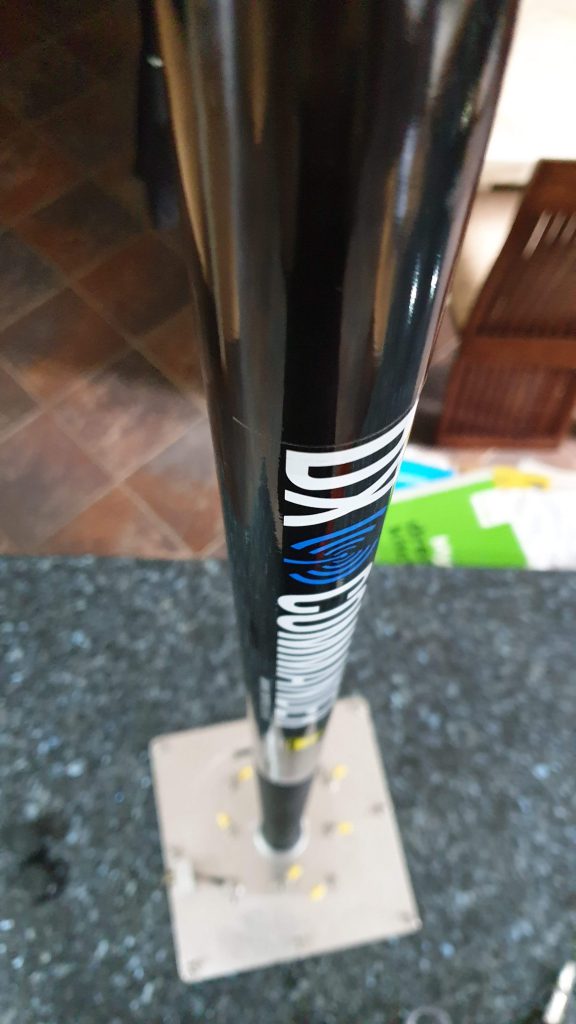
So, unless you have been living under a rock you will have heard of DX Commander. M0MCX, Callum, runs a micro antenna business producing mostly multiband vertical antennas. He also runs a very enjoyable YouTube channel.
Based on a ‘fan dipole’ idea, half of the the dipole is taken and turned on end, and driven elements for each band run up a vertical fibreglass flag pole. With a suitable ground system deployed a multiband HF vertical can be achieved very quickly. Research paper after research paper shows that diminishing returns are reached with roughly 4 times the amount of copper down as the wavelength of the lowest frequency band. So, if you want to reach those diminishing returns on 20m for example, you need something over 80m of ground radials, and don’t stress making them 1/4 wave or anything, just any old length, 20 to 30 radials of 4m each would be fantastic. Just chuck them down and get on the air !!!!
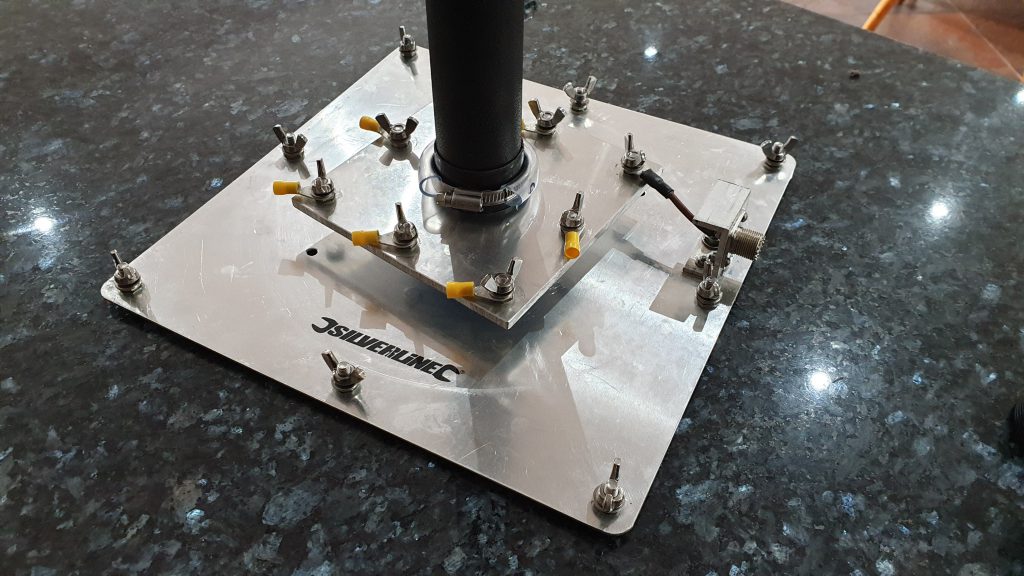
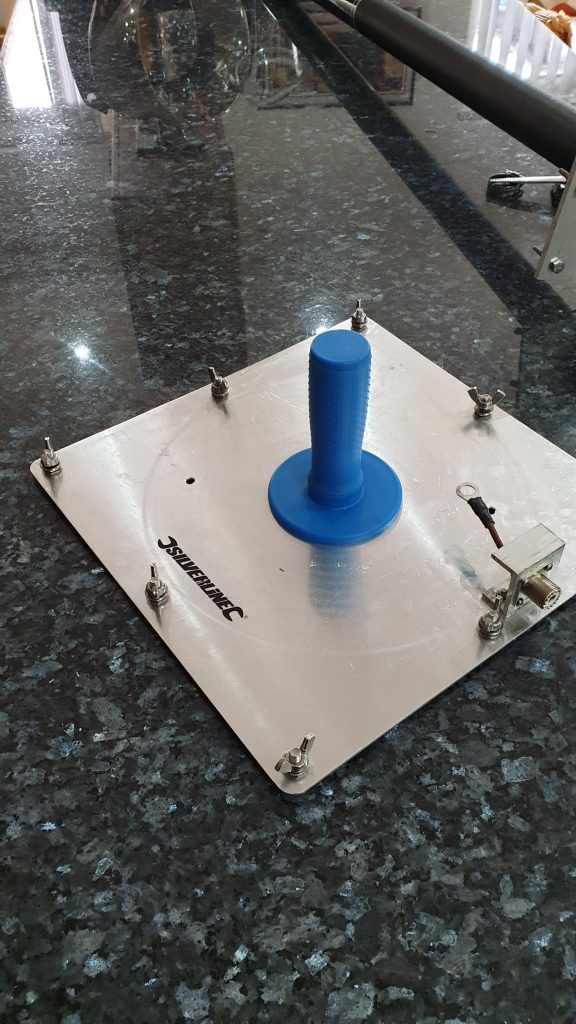
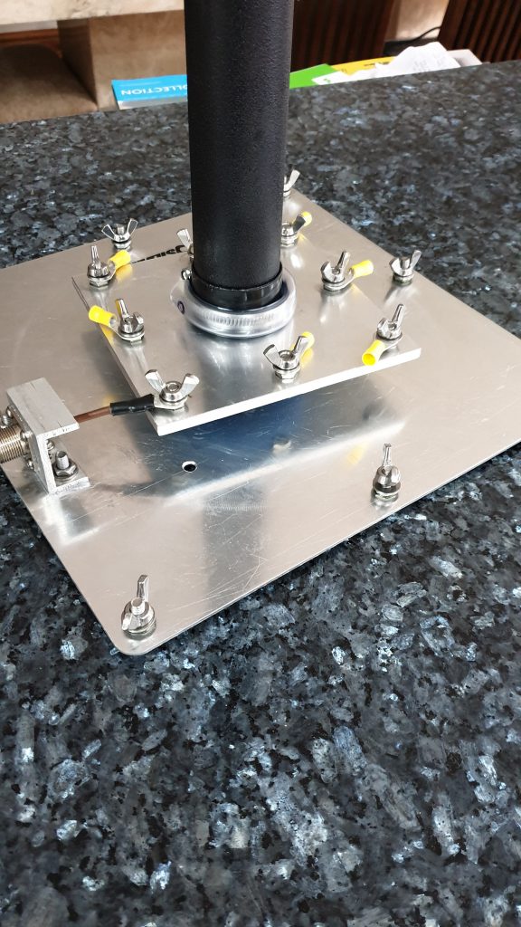
Anyway, with the ‘technomagic’ aside, I decided to built my own home brew version. I am using an aluminium plasterers hawk, upturned to act as the ground plate to attach all the radials to. Drilled and tapped, suitable bolts and an so239 attached, it is very easy to deploy. A couple of holes can be made to push tent pegs through.
I picked up a DX Commander 10m fibreglass pole. The end cap can be removed and it sits nicely over the handle from the plasterers hawk.
In Part 2 I will build the ‘spacer plates’ and get the elements cut for each band I want to operate on.
73 for now !
ICOM-7851 RFI issues
A quick follow up.
So, my friend had problems with his IC-7851 doing strange things. After hours of diagnostics the issue was found. The interlink cable between the STEP-iR control box and the CI-V port on the back of the radio seemed to be causing the USB disconnects and other gremlins. With the interconnect removed, all problems vanished.
We tried ferrite after ferrite on that cable to no avail. Either the early generation STEP-iR control box has insufficient RF attenuation, or there is some other issue, perhaps with the ic-7851 or the data/control cable from the tower to the STEP-iR control box. Either way, with the interconnect removed, and consequently no auto control of bands, then the problem goes ‘away’.
73
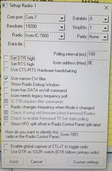
ICOM-7851 musings
A friend has been having some issues with his new, rather gorgeous, ICOM flag ship radio, the IC-7851. CAT issues, com port issue, cw keying issues, STEPir tracking issues. This post is really to act as a record, and perhaps help anyone else with similar problems. All related to configuration, possible conflicts and other such annoying gremlins.
So, after removing the icom usb drivers, unplugging the usb cable, and reinstalling the drivers, then reconnecting the usb cable, the radio and computer seemed happy. COM7 and COM8 showed up in device manager. However, there does seem to be an issue where upon reboot, sometimes the USB devices will not be recognised. This issue is to be monitored and some more work perhaps required figuring out what is happening.
Moving on, we managed to get the radio talking to HRD and Logger32, at 19200 baud, 8n1, no handshaking, on COM7.
We then looked at CW keying over the USB cable, instead of running a separate cable and related serial interface. The IC-7851 presents two com ports as mentioned above, COM7 seemingly the CAT control, COM8 the keying port perhaps. Another friend did mention that COM8 might be second RX, but not entirely sure on that. Anyway, COM8 was used in the keying config of Logger32, and the 7851 was configured to use USB2 DTR as its CW keying source. All worked great, with CW and break-in selected on the radio.
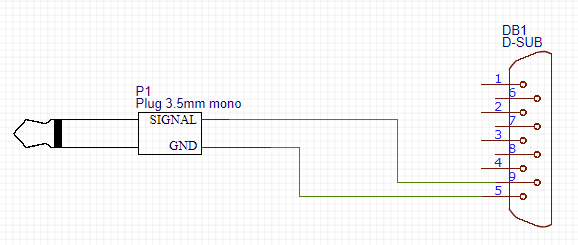
We then looked into getting the STEPir auto tracking the vfo frequency. The STEPir control box is quite an old version, pre-dating the current SDA100’s. After much head scratching, we decided to use the remote (ci-v) port on the radio. The TIP of the 3.5mm jack, going to PIN9 (ttl rx) of the 9way d-type female that plugs into the STEPir box, and the RING to pin5 (gnd). A quick solder job and it was all working. Note: the pin out of the STEPir 9 way is not standard serial, certain pins are there to be connected to different makes of radios.
It has been noted that the STEPir will only track when the vfo on the radio is adjusted, and not when Logger32 tells the radio to move frequency. The IC-7851 needs to have CI-V transceive turned on.
Some configuration settings recorded here as a record.
73!

MB7TR – SSTV repeater
We have a new local SSTV repeater, and as far as I know one of only two in the country. Classed as a ‘regenerative node’ it will relay/repeat a received image.
MB7TR is situated in Cwmbran, and maintained by MW0RPB (Peter). It operates on 144.500MHz using FM and outputs in the Martin1 sstv mode.
To get it to repeat your transmitted image, which incidentally can be transmitted in any SSTV mode, you need to do the following, all on 144.500MHz in FM :
- TX your CW ident (good practice)
- TX a 1750Hz tone burst for around 1-2 seconds and key off
- Listen and wait for MB7TR to reply with its CWid – this signifies it is ready to repeat
- TX your SSTV image
- Sit back and wait for your image to be repeated out
You can use your SSTV software of choice, MMSSTV being mine. It is working great, after a few teething problems Peter has ironed out all the gremlins. Give it a try, you never know who might reply !!

PI7CIS VHF beacon
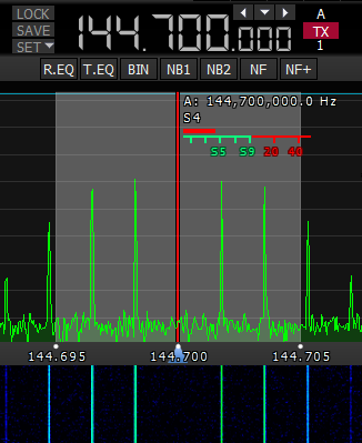
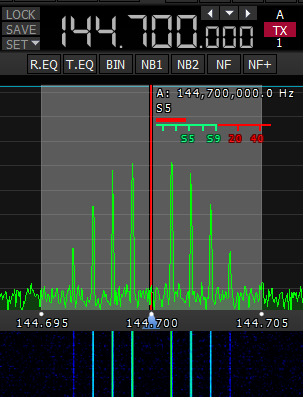
 I had the beam pointed at GB3VHF but noticed another signal on the waterfall around 144.415.590Hz. I moved the beam to 80 degrees, and it was the PI7CIS beacon on the sea shore of Scheveningen, around S3-4.
Using CWGet I decoded the following CW around 11:36UTC, 6/6/18 :
pi7cis jo22dc 50w dipole 90/270
Details here…. http://www.pa0c.nl/Pi7cis/pi7cis_vhf_beacon.htm
73