ToyoCom TCO-613 5MHz frequency test

A friend and fellow amateur radio enthusiast, Ross GW3NWS, let me borrow one of his TCO’s, a ToyoCom 5MHz unit.

Pin-outs of the ToyoCom TCO-613

As I wanted to obtain some higher accuracy to the results, I decided to use the 9th harmonic at 45MHz. The signal was observed on a SunSDR2 Pro, that had been provided with a GPSDO 10Mhz reference signal.

The TCO-613 was powered up from cold, the following was observed, again using WSJT-X in FreqCal mode. After 12 minutes the TCO settled to around 0.43Hz high at 45MHz, an average of the last 8 minutes of delta frequency. The test was concluded after 20 minutes. No adjustment had been made and was tested as provided by Ross.

ICOM IC-705 Frequency Stability 1

Since I recently modified my IC-9700 with a Leo Bodenar master reference insertion board providing it with a GPSDO locked master frequency of 49.152MHz I have been looking at drift of a number of my radios. I decided to test the IC-705.

COOL DOWN

I set the IC-9700 to transmit a carrier on 439.999MHz into a dummy load @ 0% RF (perhaps 1-2W not tested). This transmission was performed for 2hrs and monitored on the IC-705. I dropped the RX gain on the IC-705 and offset the VFO -1.5kHz so that I could monitor it using WSJT-X in FreqCal mode. The audio was taken from the IC-705 and provided to WSJT-X. The carrier would now show at 1500Hz in the audio passband in WSJT-X. The FreqCal mode shows delta frequency from this 1500Hz middle point.

I do not have any temperature values, however the in built temperature display was observed at the start and end of the test. The orange bar shows the swing, from high (right side) to low (left side).

Tannoy Reveal 502 issue

So, one of my Tannoy Reveal 502 speakers kept blowing its T500mA fuse. I purchased some replacements, tried a new one, and pop. Something was obviously wrong.

The cabinet was a bit awkward to open, but I needed to get in there and have a look. The outer screws removed I poked something soft(ish) through the front port and ‘persuaded’ the back panel to come loose.

After a quick visual inspection I noticed that C11, a 100nF decoupling? capacitor, looked very hot and burnt. I did a quick check at this point and sure enough there was a short somewhere on the +ve and -ve rails.

Out with the soldering iron, I removed C11 and C6. C11 disintegrated as it was being de-soldered, and was obviously defective. I also removed the two 3300uF caps and gave them a quick test, they seemed fine. With those two re-soldered as they were ok, I replaced C11 and C6 with some 104’s (100nF) ceramics, and ran some tests with a new fuse in place. All seemed to working fine, sounding great. I left C6 and C11 on long legs to move them into some free air to try and reduce the chance of over heating. The yellow ‘hot snot glue’ was a nightmare to remove and was more like epoxy.

I must say, the ‘psu’ board did not seem to be of high quality. It looked as if it had been put together on a Friday afternoon, caps at all sorts of angles, rectifier twisted, just shoddy workmanship. I didn’t remove the amplifier/filter board so I can’t comment on that.

Anyway, a simple fix and I once again have a right speaker ! Happy days.

BBC Micro Revival – Model B 32k

owlWell, over the years I have had loads of computers, some home brew, some commercial. They have come and gone, however, my Acorn BBC Micro – Model B 32k has always followed me around.  It was purchased second hand some 30+ years ago, after selling our beloved Acorn Electron. I can remember my mum taking me into a computer shop in Newport to look at a Sinclair Spectrum 128k with cash in hand, and telling her it would be ok to park on those lines as we were only going to be a minute. How wrong I was – parking ticket and clip around the ear later 🙂  My brother and I decided to go for a BBC Model B instead, and due to the price, second hand was the way forward. One was found, from a family in Bassaleg I seem to remember. Anyway, enough of the back story….

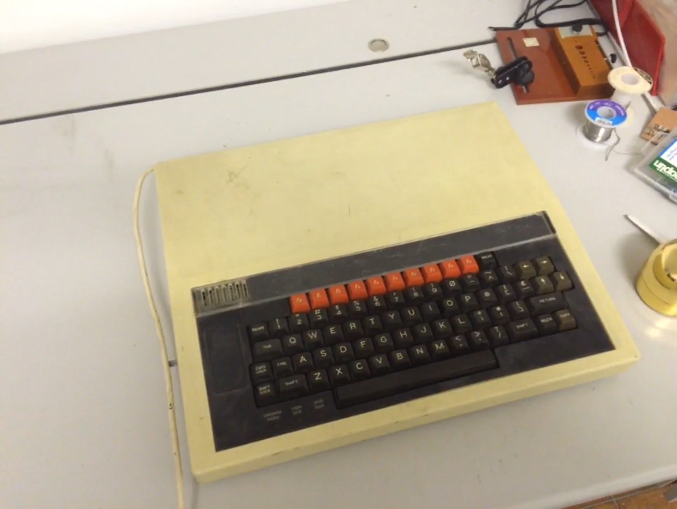
Or perhaps not….  For a good many years of my childhood, my brother and I used that BBC Micro, together with a friend Chris McCray we spent many a weekend, tweaking that, bodging this, downloading via prestel/teletext, listening to Music 500’s and other shenanigans. Fast forward 31 years, and my BBC Micro – Model B was in a sorry state, and would not switch on.

bbc1

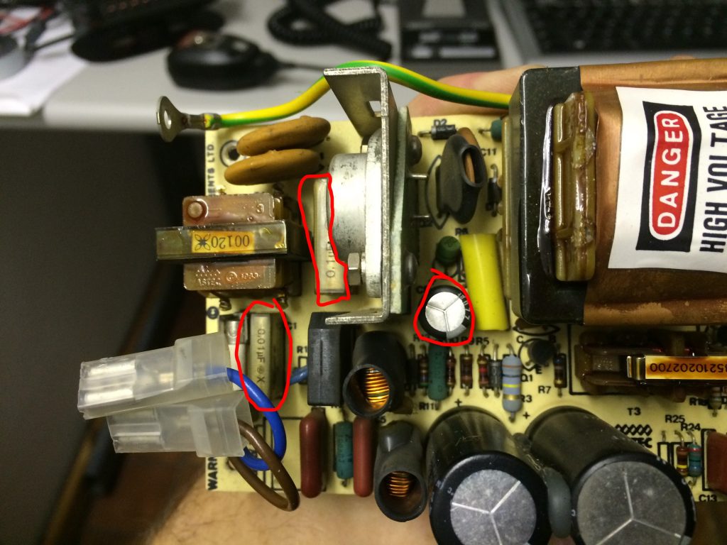
After some diagnostics, I discovered the PSU was not working, a bunch of capacitors need changing, specifically C1, C2 and C9 in the PSU.

  • C1 (0.1uF (100nF) X2 class capacitor) @ 250VAC (or higher)
  • C2 (0.01uF (10nF) X2 class capacitor) @ 250VAC (or higher)
  • C9 (220uF electrolitic capacitor) @ 10V

b2

For simplicity, I picked up a kit from sprow.co.uk, just to get the PSU working again, and after 30 mins or so, the familiar double tone was heard. I will eventually change all the electrolytic caps in the PSU for peace of mind.

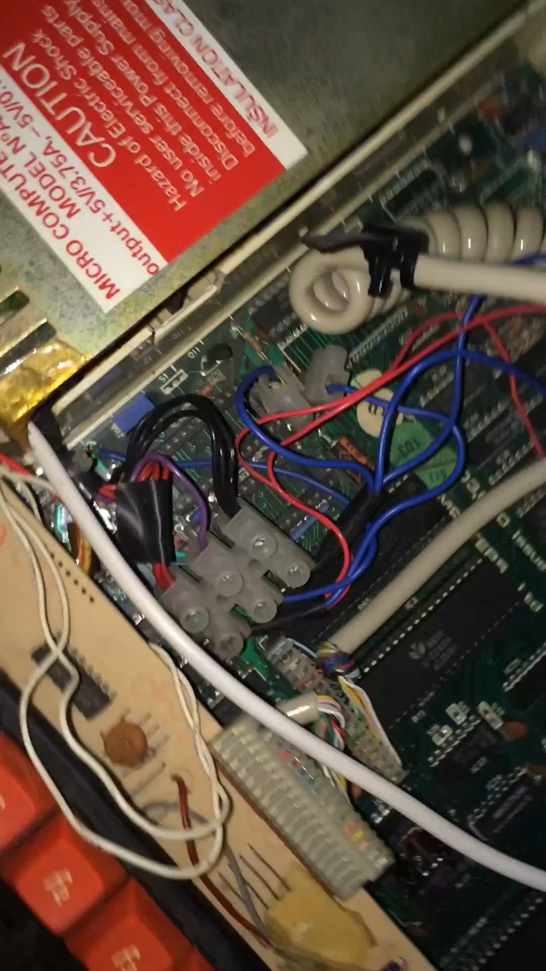
Everything had the looks of a 10-12 year olds bodge stamped all over it. Wires tacked in here, solder blobs there, a complete nightmare inside.

satate3 state state2

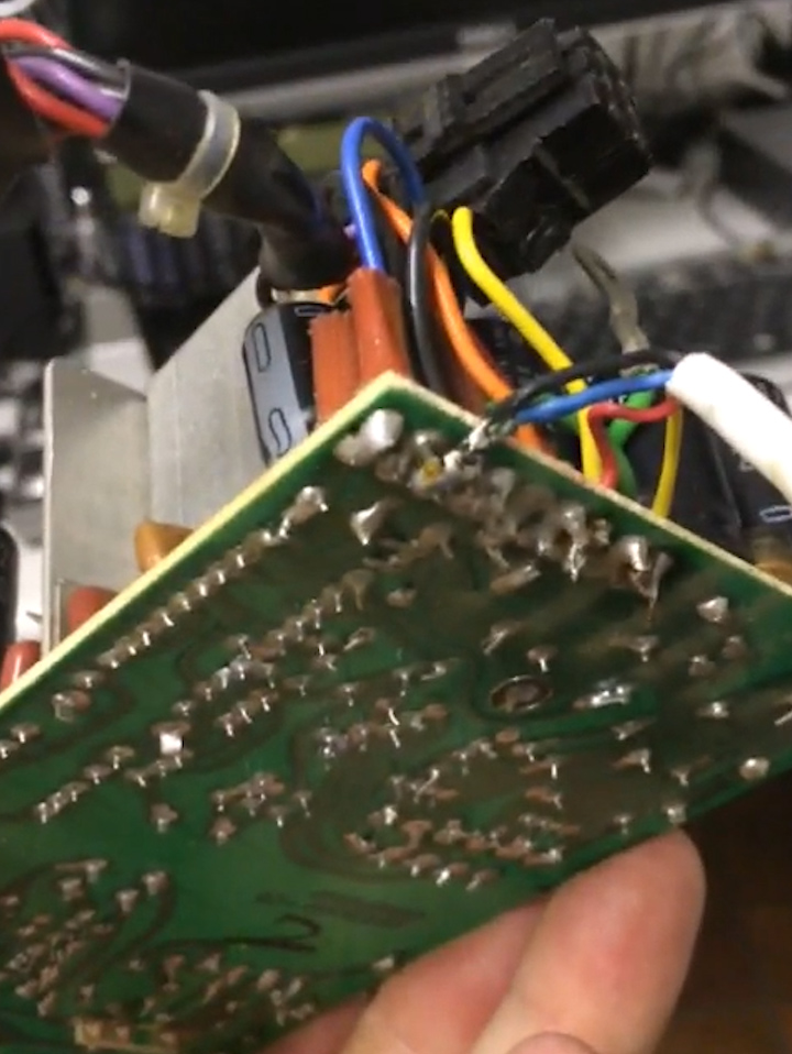
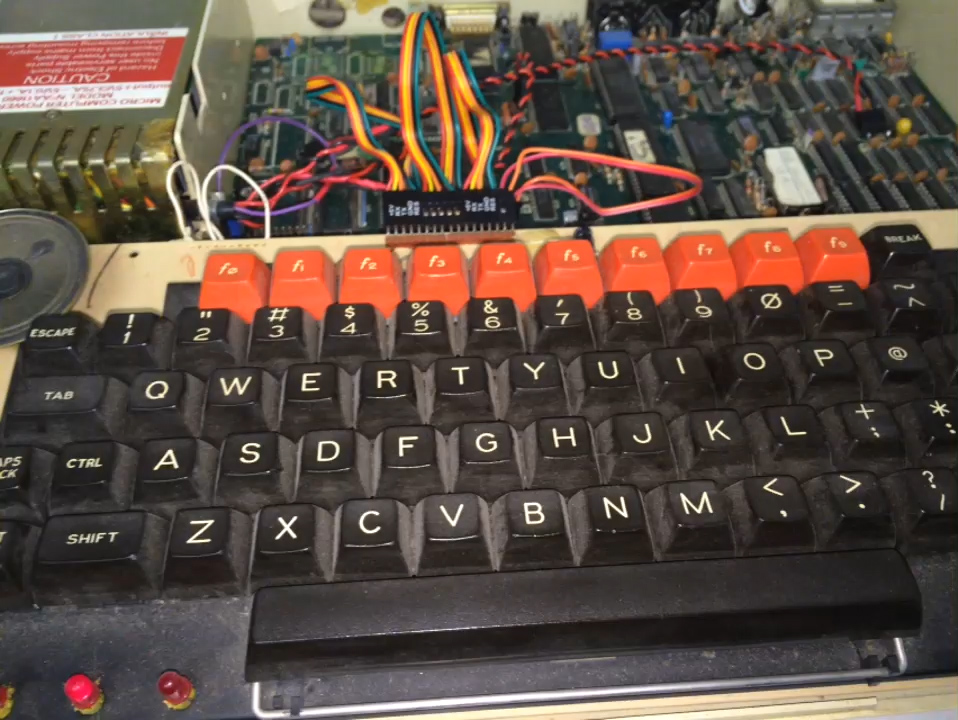
So, I pulled out everything, all the junk wires, the dodgy keyboard cable (which came from an old case that used to house the computer and had a remote keyboard), the 10k pot on cables for volume, chock blocks, it all got cleared away.

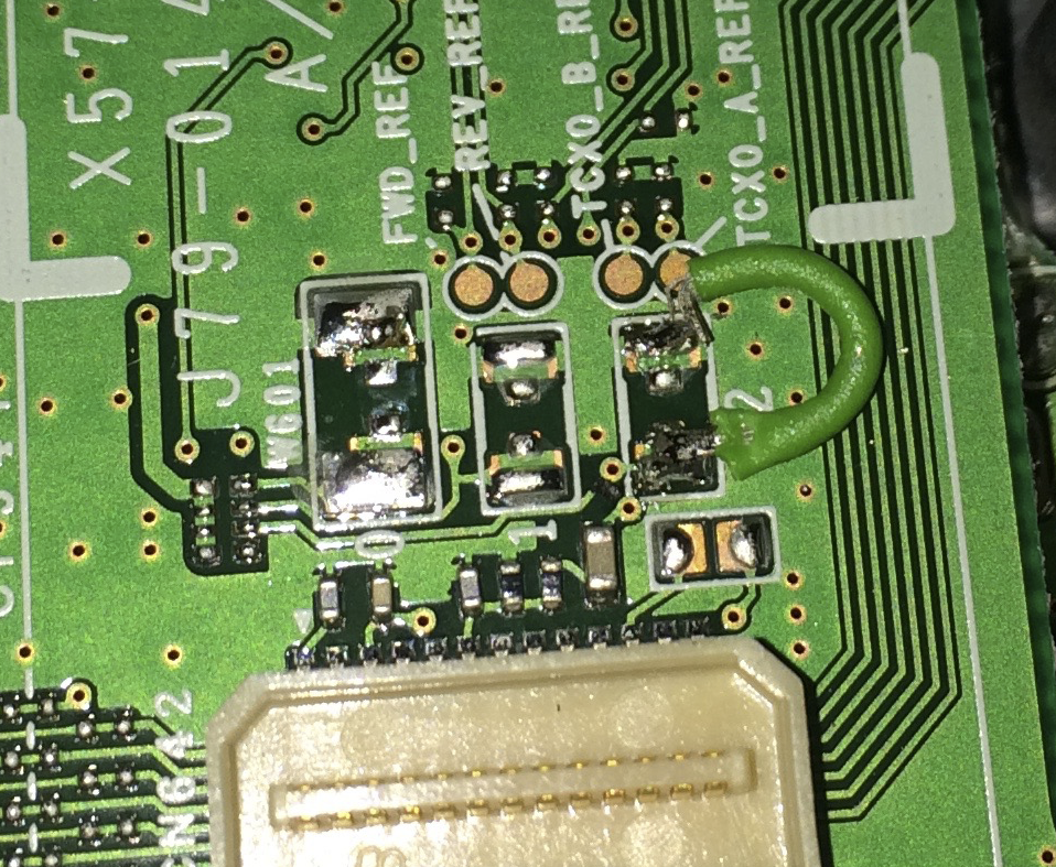
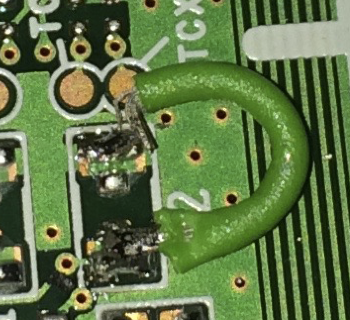
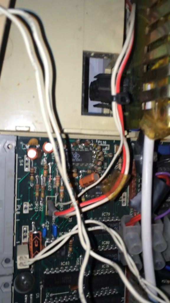
I replaced all the power cables, however some of the spades had snapped from the mother board, so I replaced those with dil header pins. The CAPS lock key on the keyboard seemed to be faulty, and after investigation the pad had been pushed off from the board. A small jumper to a piece of track fixed this.

tidy1

tidy2

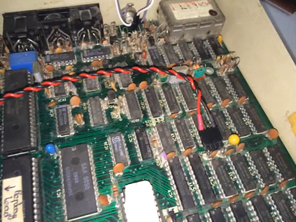
The composite video out connector needed fixing, the wires had been ‘ripped’ out of the motherboard.  Things were getting better and taking shape. I gave the board a general clean up with some isopropanol and a q-tip.

After some testing I noticed that the audio seemed rather quiet and would often crackle and become inaudible. I replaced the 10k pot with a 3296 variable resistor, not the ideal solution (needs a stupid number of turns, but hey ho).  I decided to replace all the electrolytic caps on the mobo, so this was the next job, relatively easy.  Audio still unstable, I decided to replace the LM386N audio amplifier 8 pin chip and swapped out with a modern replacement, which was not the best thing to do. The old chips were 1W, this new one 0.25W, so even quieter.  I have noticed that the audio crackling has been reduced but not completely removed. Next plan is to swap this LN386N with a NJM386BD which is a 1w equivalent. I am also planning on swapping the quad op amp LM324, the chip before the LN386N.

I also picked up an MMC userport solid state disk drive, to act as a data store for the beeb, having lost the 40/80 track 5 1/4 inch drive over the years unfortunately.

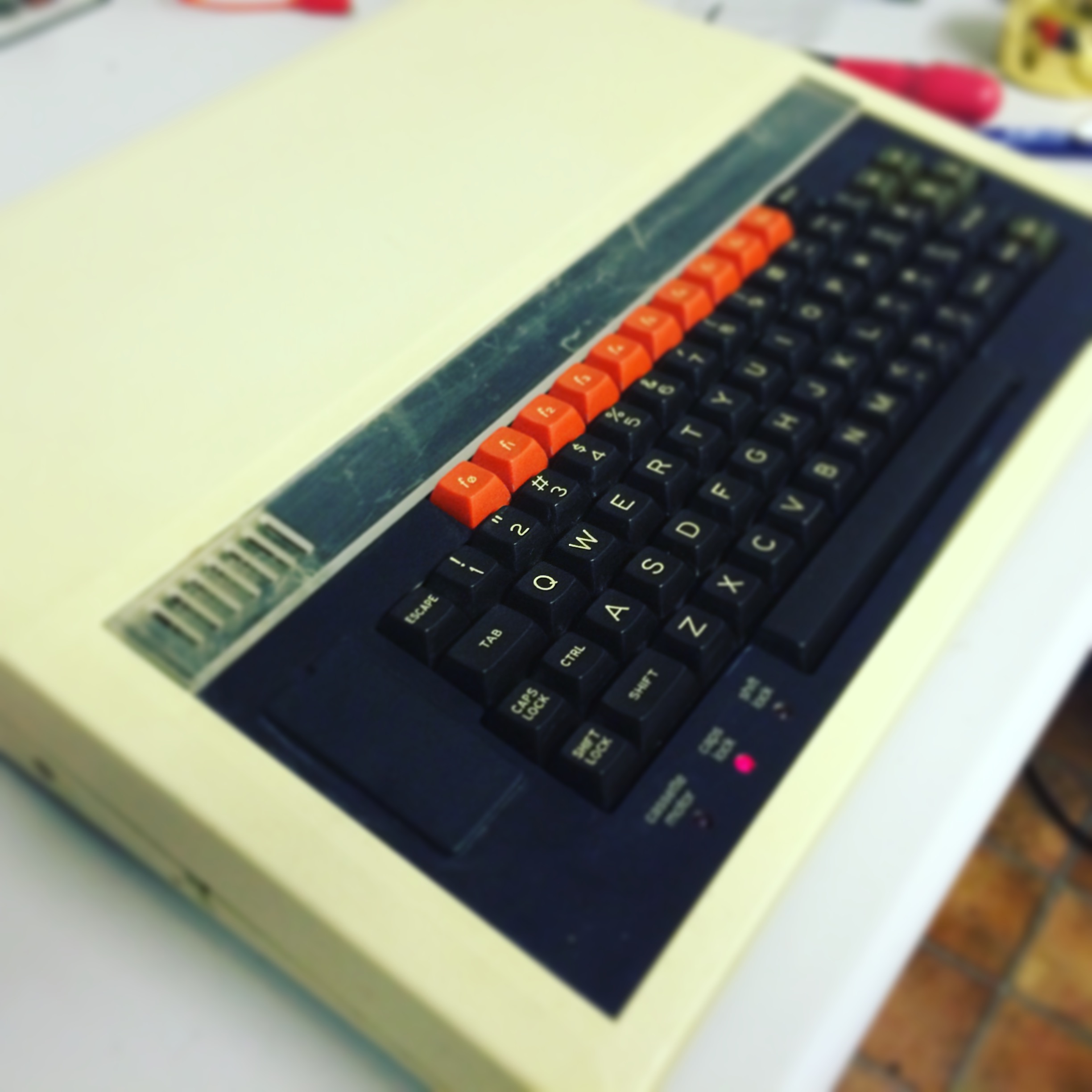
Upcoming plans are to replace the remainder of the PSU caps, fix some ceramic disc caps that have been chipped by extracting roms, connect it to a vga monitor via a gfx interface board from the ttl rgb output, get the old music 500 working and a number of other simple jobs.  Chuckie egg, revs, elite and a bunch of other games were tested, and ran perfectly. Oh, I did enable colour on the composite out just to test things before the gfx board turns up.  This final picture shows her with her lid back on. Happy days 🙂

final1

TVi – The battleground

Television interference, what a complete nightmare. When I passed my foundation licence and started transmitting on 2m @ 10 watts,  TVs throughout the house all went haywire.

We were running a Global (or equivalent) F140 amplifier/splitter 4 way, to take signals from the loft mounted (not ideal, being in a bungalow) TV antenna and distributing them to some TVs around the house.

So, on day two of being on the air, I replaced the loft antenna with a high gain, and replaced the shoddy down feed coax.  This did seem to improve things, until recently, when I moved into a new shack location and was spending more time on 2m and 70cm. Also transmitting at up to 50W with the new callsign.

Anyway, it transpires that the F140 amp, is wide band, in that it amplifies from 48mHz through to 700-800 odd. This is not ideal considering some of the HAM bands fall inside this range.

So a scout around, and some advice from 2W0ODS (Dale), I decided to pick up a PROception PROAMP104X distribution 4 way amplifier. £11.98 from a local supplier ToolStation. Keep in mind it doesn’t come with a 12v PSU. It has a frequency response of 470-862mHz, and has >= 26dB of rejection below 400mHz. The passband filter slopes from 400mHz at -26dB up to 470mHz at roughly +4dB.

Screen Shot 2016-01-04 at 16.13.42

A link to the UK distributor of the device can be seen HERE and includes links to manuals. You can get it cheaper from ToolStation though.

So, I returned home, installed the device in place of the old F140, F-type connections on both, so an easy swap over, and the existing 12v supply was in spec, so that was used.

I did some initial tests on 145.375 and the signal was maintained on various channels on the TV whilst I was keying, un-keying and talking. Another test made on 70cms to a local repeater GB3RT, and the TV picture was perfect.

Fingers crossed I have seen the last of this issue. One last option if it rears it’s ugly head is a ham band tvi filter on the input to the splitter, to further reduce unwanted signals.

Fingers crossed, and 73 !

50 ohm Dummy load – on the cheap

Well, I decided I needed a dummy load. I ordered a bunch of 3w @ 510 Ω to put in parallel, so roughly 30W handling (perhaps more with the added cooling for short periods).

So, 10 of them soldered up to some scraps of vero, and a reading of 50.6 ohms taken, so all is good on that front.

solder_weld

I added the so236 to the tin lid, and solder/welded it all up. It will be sitting in a Golden Syrup tin, with a 500+ml of mineral oil. I had to silicone around the underside of the so239 to prevent the oil from oozing up through the connector.

IMG_3140      can_o_whoop_ass

IMG_3142

Ah, job done, and a total cost of less than £8 🙂

73

X10 to CBus conversion – Part 1

My mum’s house has a rather old (some 8+ years) X10 install, which was showing signs of needing to be replaced. The alarm system was also having a few issues, so we decided to strip it all out and start again !  There are some 79 X10 modules, which consist of dimmers and relays. The alarm has 48 zones and is a Cytech Comfort system.

A decision was made to invest in CBus 2 and Cytech Comfort 2. We would be running LED bulbs on the CBus system, so an investigation process was undertaken to find suitable compatible bulbs with CBus (yes no one could tell us what to buy). I tested about 6 makes, and MegaMan were the ones to go for. Smooth dimming and no flicker. They worked great ! Mum decided that she wanted Daylight temperature led bulbs, some 6500k. The bungalow has always been quite dark inside, so this might be a welcome change.

So, time to rip it all out ! The old wiring mess :

x10

I ripped all this out with the help of my brother (Julian) and labelled up every wire. Roughly 150 twin and earths. Half of them were pulled up through into the attic space as they are not being used in the new system. These redundant wires were from momentary switches to turn the x10 modules on and off, essentially the light switches in each room. The new CBus system works on a low voltage over Cat5 network (star, bus) to communicate with the wall switches in each room and our father who built the bungalow ran Cat5 to each light switch for future proofing.

So, we starting making a mess !!!

 IMG_3023 IMG_3018

So a plan was formed, and the first CBus modules was installed. Each module has 8 x 1amp dimmable lighting channels.

IMG_3024

Slow progress was made, routing wires and ensuring all labelling was accurate.  There will eventually be some 32 lighting circuits to different rooms and areas around the bungalow, and 12 x 10 amp relay circuits for items such as pond pumps, cabinet low voltage lighting, bath room fans and other such loads that do not require a variable supply, but one that is off/on.

So after a few days the chaos started to take shape…

IMG_3053

IMG_3052

Each dimmer channel goes through a 1 amp MCB, and each relay module has a 6 amp MCB protecting it. At the end of the channels we are running various MEGAMAN led light bulbs.

The next post sometime later this week will see the lighting system completed, and a start on the Alarm system will begin next week.

Cheers !

PS: no blue smoke has been released in the change, and mum loves her new daylight bulbs and touch sensitive switches.

Kenwood TM-D710GE Update

Well, the new one just arrived from ML&S, and it is like night and day. What a difference, fantastic job.   The mod involves moving that 0 ohm surface mount resistor from PAD 0 (the right one in the image) to PAD 2 (the left one in the image). This enables wide band, and cross band repeat.

Thanks to ML&S who did a great deal on it, arrived early next day, and top quality soldering and mod work !!!! I am well happy 🙂

73

ml+s_soldering_mod

TM-D710GE – what a nightmare

So, about 3 weeks ago, on a Tuesday, I placed in good faith an order from a large HAM internet retailer here in the UK for a Kenwood TM-D710GE. A rather large investment into what hopefully was to be a high quality piece of kit, that would last me many many years.

I received a phone call sometime after that same day to advise me that they were in-fact out of stock, at which time I asked if they could perform a wideband mod, and crossband repeat mod.  The radios should be at the retailer on the Friday, so I let the order process carry on as I was in no immeadiate rush.

Monday came with no notification of shipment, but it did arrive on the Tusday, after another phone call on Monday afternoon to find out what was happening.

The radio arrived on the Tuesday a week after ordering, however, there was something seriously wrong with the audio quality. The radio had to be on max volume to hear anything. The mylar speaker in the main base unit had been popped from the inside, somehow, either during manufacture, or as part of the modification work.

See this video on what we needed to do to get it working.

Anyway, after some use, it transpired that the cross band repeat mod had not been done. So the retailer arranged collection on the following Monday, took it back, did the mod, and I received it back today.  Now bear in mind I had previous conversations with them explaining that the 0 ohm from PAD 0 had to be moved to PAD 2. They needed to get confirmation from Kenwood apparently, that the cross band mod was ok to do, leading me to think, they had not actually done this sort of thing before.

So, it arrived back today, we took the lid off, and the following was seen….. what a BODGE !!!

Frayed wires, no 0 ohm resistor sat there nicely, what a mess. I should have been sent the removed 0 ohm resistor when it was removed, but no. It was probably swept aside in a deluge of solder.

shoddy1 shoddy2

I called and emailed the retailer with pictures, and the upshot of it all is, they are collecting it again and giving a full refund. To their credit, I didn’t have to ask for a refund, they offered it me directly as their only ‘professional option’.

I’ve now ordered from another major retailer, with the same requests for the mods, and I should receive it tomorrow. I’ll keep you posted !

What a nightmare !!!!  arggggghhhhhhh

73