QSL Card Design

Well, it is about time I designed a QSL card. I wanted something that represented Newport and S.Wales. I stumbled across an artist, Rhiannon Ash, who has done some lovely water colours of some of the Newport heritage. These are the final designs for the front and back of my qsl card.

3d printing – a dipole centre and a balun

So, after seeing some of the creations from a few friends, my brother and I decided to go 50/50 on a 3d printer.  I really needed a small dipole centre and balun combo, capable of 100w tops, so I decided to go about making one.

Some designs in TinkerCad, a few tweaks here, a few there, and the case was complete, together with a number of different plates enabling custom, so239 and bnc connections. The case would eventually house a 1:1 guanella current balun, using a fair-rite type 31 core.

screen-shot-2016-09-08-at-12-13-59

The case went through a number of iterations, and prints. The above design was the finalised version (hopefully, lol).  The T clip you see in the design enables the dipole centre to be attached to a painters pole or slid down a fibre mast.

I am only printing in PLA at the moment, so the balun will not stand up to 365 days a year outdoor use.

img_4264

Anyway, the printer is nearly finished cooking another, so i’ll sign off here.

73

Richie.


New Call Sign – MW0LGE

Well, after lots of study, and an agonising wait I now have my full call sign, MW0LGE 🙂

Thanks to Ross (GW3NWS) at the Newport Amateur Radio Club, and all those involved with the Bath distance learning course especially Bob Jones (GW4FCV) and Steve Hartley (G0FUW).

73 🙂

Another 2M tape measure yagi

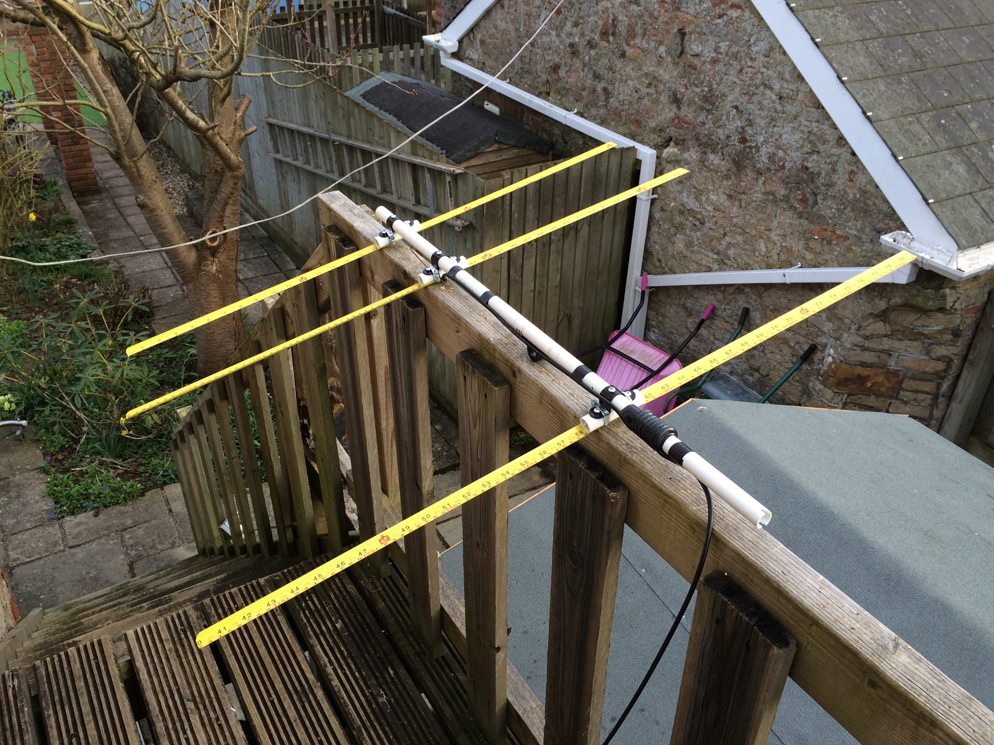
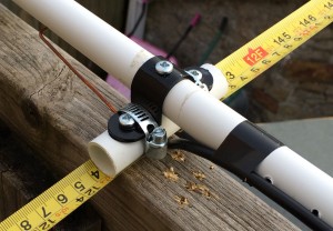
Last year the Cwmbran and District Amateur Radio Society staged a fox hunt and a number of us built 3 element tape measure yagis using measurements provided by a fellow club member, Pete MW0RPB.  This year I decided to rebuild mine, and rework the dimensions using a great yagi design program from John Drew – Yagi Calculator. I used jubilee/pipe clips, some plastic conduit, conduit saddle clamps and a bunch of screws. It should be noted that for these calculations the dimensions of the elements were 21mm wide and 0.5mm thick, with non metal boom.

fullyagi yagi_construction

Design frequency was 145.000 MHz the centre of the band.

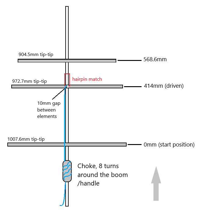
Reflector length 1007.6mm tip to tip, solid, at 0mm boom position (the start position)
Driven length 972.7mm tip to tip, with a 10mm gap, at 414mm boom position
Director1 length 904.5mm tip to tip, solid, at 568.6mm boom position

Note: The driven is tip to tip measurement, this includes the 10mm gap at the centre. The boom positions should be marked on the boom from one end, starting at 0mm then 414mm and finally 568.6mm.

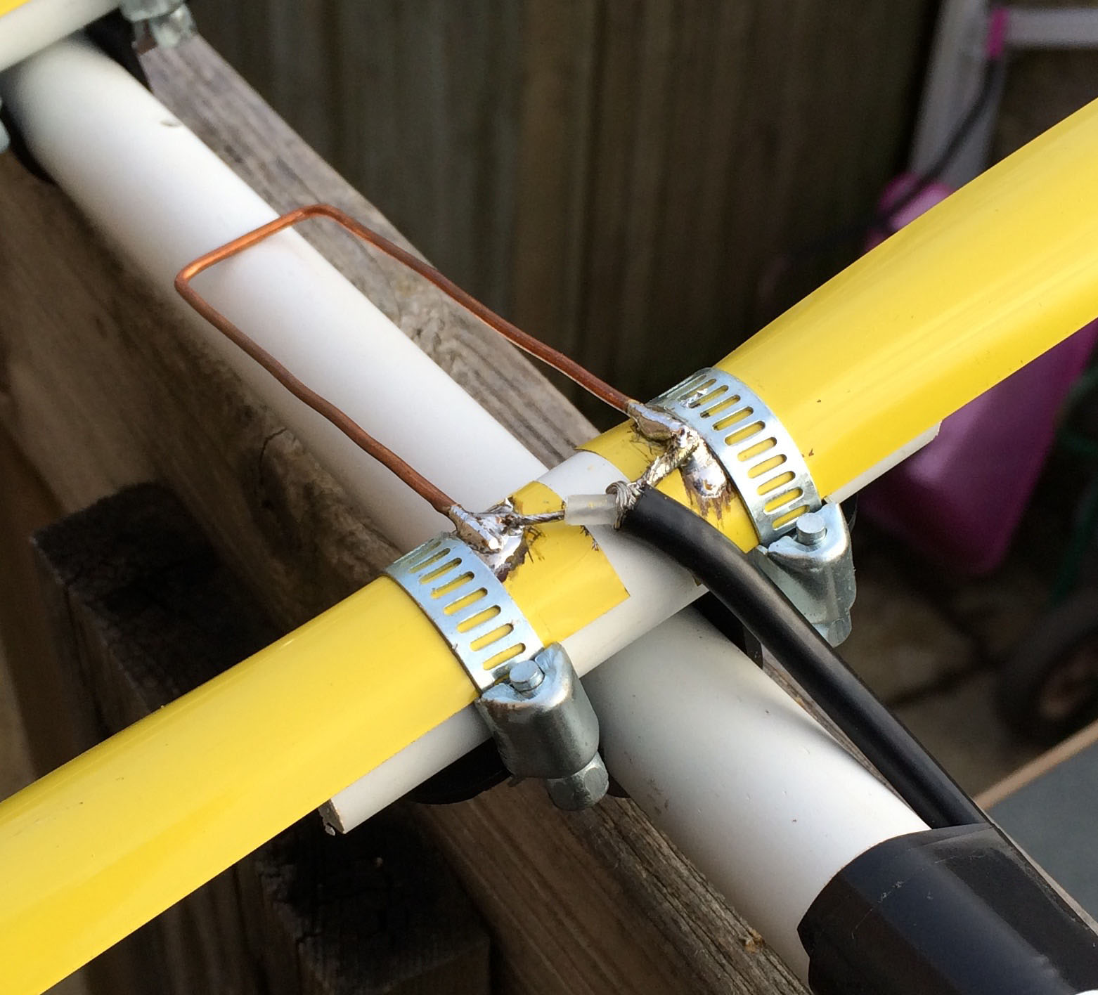
A hair pin match was made from some 2.5mm bare copper wire (from twin and earth mains). The dimensions for this 85mm long and 25mm wide. The paint/covering on the tape measure was scratched off/filed and tinned heavily.

hair_pin

The coax feeder was cut to and odd half wave length (* velocity factor) of the design frequency, 0.66 being the VF for RG58. The number 5 being an odd number of half wavelengths long, you can pick any odd number for this to give you your length of coax. Have a read of this if you are interested in why this is done.

feeder length (meters) = ( (150 / 145.000) * 0.66 ) * 5

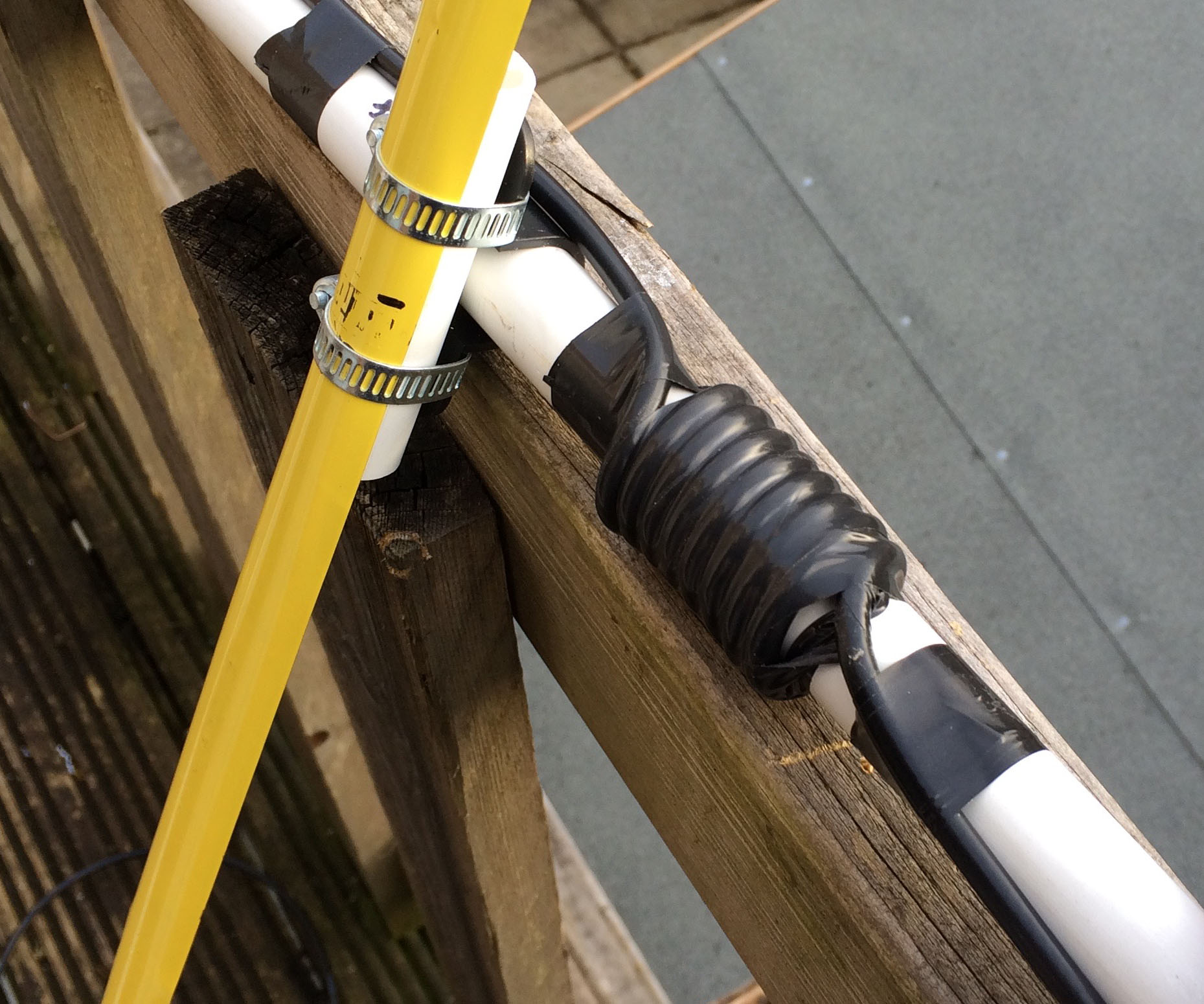
An RF choke was added at the end of the conduit using some of the feeder, so make sure you pick an odd wavelength long enough to include enough for the choke.

rf_choke swr_curve

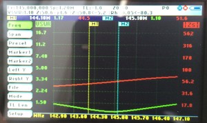
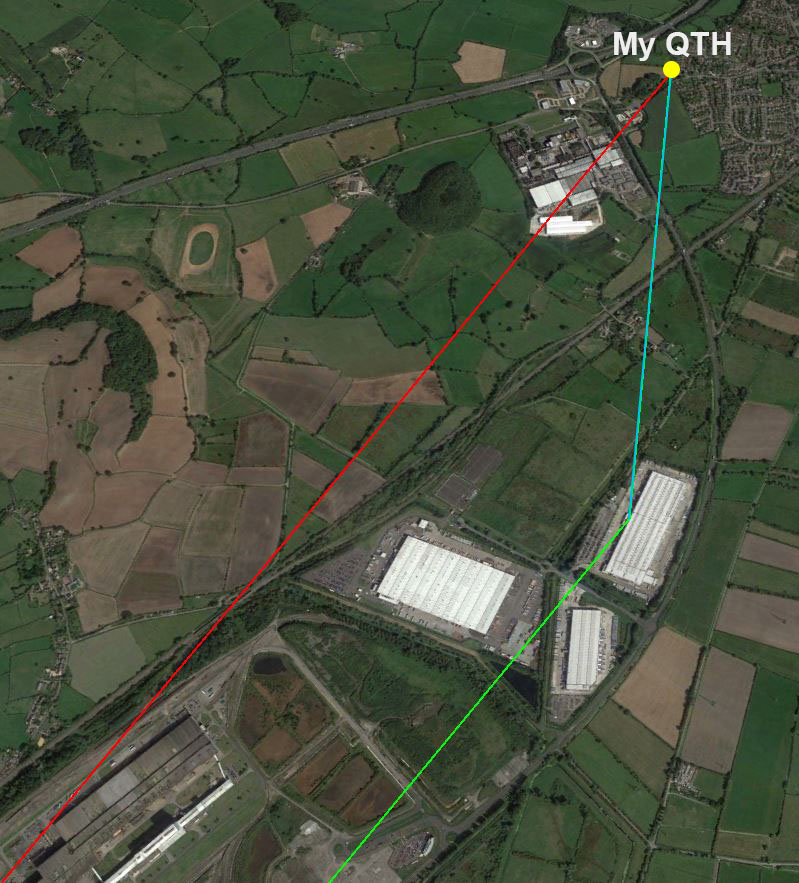
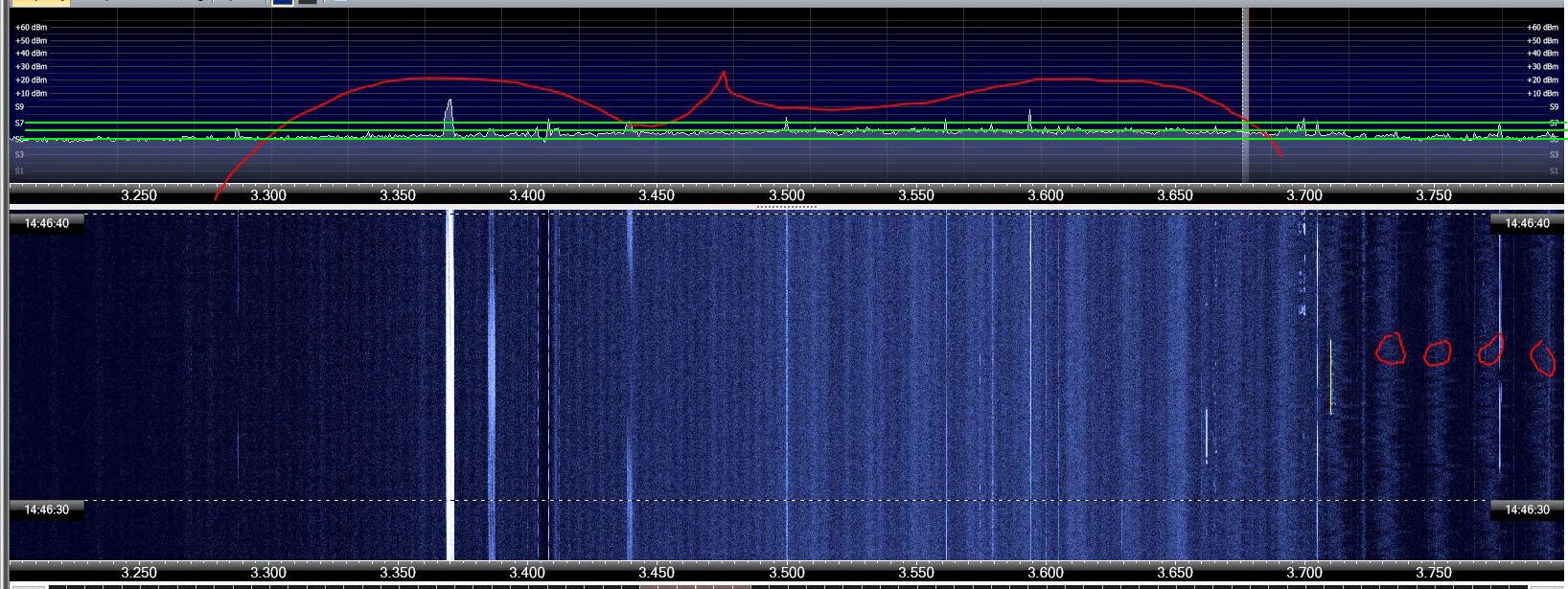
The results speak for themselves, what a cracking antenna, see the swr plot above (thanks George for the lend of the Sark-110).  I had a QSO on 5w with a station 37 mile away from Magor, on the ‘white horse hill’. The 3 ele giving 6.9dBi gain.

Have fun making yours !

73

Upgrades !

I decided to add another two directors to make a 5 element yagi. I found some 22mm alkathene that would slide over the conduite and allow me to extend the boom.  The 5 ele giving 9.9dBi gain.

Director2 length 894.6mm tip to tip, solid, at 940.7mm boom position
Director3 length 885.5mm tip to tip, solid, at 1115.2mm boom position

Signal reflections – Fox Hunt pitfalls

So in readiness of the upcoming fox hunt (an exercise in direction finding), I disassembled my existing 2m ‘tape measure’ yagi and rebuilt it with some re-worked numbers. I will do a full article on the construction at some point.

I wanted to do some testing with Dale, 2W0ODS, his QTH is the other side of Newport. Anyway, 2m FM handy and the new ‘tape measure’ yagi in hand, Dale started giving a prolonged over via his omnidirectional collinear. I quickly ‘zeroed’ him in and obtained a heading for max signal strength. Just to note, my qth is low down, 6m or so ASL, and behind the rise that the motorway/roundabout/brewery sits on.

See the following for the results, quite amazing :

The blue/cyan line is the direction of strongest signal with the yagi

The red line is line of sight. As you can see it passes through Magor brewery, a large lump of metal with 100’s of smaller metal barrels.

The green line is plotted from Dale’s QTH and is hitting one of the Tesco distribution buildings and is no doubt reflecting off the side of this building.

reflections

The size of the building compared to the 2m wavelength is of many orders of magnitude greater. To get an idea of how big something needs to be to ‘reflect’ a 2m signal then you only need to look at the size of the reflector on the yagi itself, something like 1005mm.

This was great to be able to visualise the signal path, and perhaps that Tesco building is making it possible to talk to Dale on 5w the other side of Newport.

Remember, fox hunt and direction finding can at times lead you ‘up the garden path’.

73

GB1SS downlink on 145.800

So, at around 14:20utc, today, Tim Peake (GB1SS) was due to have a chat with a school in Bristol, Oasis Academy Brightstowe (GB1OAB).

I set up the IC-7100 to listen on 145.800 +3 or so kHz as he approached, moving to -3 or so as he left over the horizon.  The following video is the audio recording, all done through the 7100 qso recorder. The antenna being a 2/70 collinear vertical, the X510N from Diamond.  I found it interesting how his signal dropped as he was over head, obviously hitting the antenna end on.

73

QRM on 80m

So over the past few months, perhaps four months, I have noticed what can only be described as some wide band QRM on the bottom two thirds of 80m and some smaller stripes of QRM near the top end.

In this image you can see the noise, it is roughly an S point or so, but quite wide band with no real strong centre frequency.

80m_noise

Direction finding it will be extremely difficult if not impossible due to its ‘spread’ out nature and lack of strong signal to ‘home’ in on.

The horizontal green lines in the top section of the image are at S5, S6 and S7. Anyway, this is more of a record of the QRM to see how it changes over the coming months.

73

Back on the air

So after moving into his new flat at the end of 2015, it was time to get 2W0ODS (Dale) back on the air. I placed an order for a couple of 6m ally scaffold tubes (5mm wall) and split the delivery with Dale. They arrived after some coaxing from the supplier and Dale picked one up and took it back to his home QTH on the car roof rack.

IMG_3388

Work was started around 10:15am yesterday in the glorious sunshine, the air cold and fresh with frost in the shade lasting all day. The first plan of action was to recce the situation and work out where everything was going. Dale’s garden is roughly 15ft square so we decided the 6m mast/pole would be as far from the house as possible. A corner was selected due to the number of concrete fence posts making it extremely strong, and a 50ft+ Silver Birch tree, the candidate for the end of the inverted L.

GW4BLE (Steve) arrived later in the morning and Dale donned his chefs outfit and cooked up some very nice bacon and egg crusty rolls. Dale was on soldering duty whilst Steve and I built up the X50 Diamond collinear antenna. A dirty choke was added (6-8 loops of at with 6-8 inch diameter) for good measure. A fixing point was also added to the top of the mast to attach a pulley to ‘pull’ up the inverted L. Paracord was the cordage of choice with its 550lb breaking strain.

Everything was fitted on the pole and it was loftedScreen Shot 2016-01-21 at 10.50.23 into place. Three mounting points using the existing fence bolts with new nuts that pass through the concrete post, and three wood bolts. A couple of rope tie offs were also added to the post.

Next it was time to get my MFJ-269C out to check the SWR on the collinear. A fantastic 1.0:1 rising to 1.1:1 at the ends on the band on 2m, and 1.4:1 at 434MHz on 70cms. All connections were made water tight with self amalgam.

Screen Shot 2016-01-21 at 10.49.24Now it was time to work on the tree. After a number of failed attempts and bruised fingers, an M12 nut was fired over the silver birch taking with it some 18lb fly fishing cord. This was then used to pull 100ft of paracord up through the tree and over. We estimated the height of the end of the inverted L to be about 40ft. The dog bones added to the end of the L (1.5mm conduit cable in grey) and a bungee added at the base to add some ‘give’ to the system.

The SGC-237 coupler/atu fitted, with 10mm of ground wire running off to a single 4ft copper rod driven in as a makeshift ground. This will be added to with more rods in a grid pattern spaced at 4ft, and as many radials as we can fit in.

Everything was made good, and I headed off around 5:10pm, quite a long day of antenna installing. Dale was left with the connections to the HF set and ensuring all was working. Later that evening I had a QSO with him and his signal was a good 10 over 9. Everything reportedly working well and top band tuneable. As a rough estimate the wire length is in the order of 90ft give or take.

IMG_3362 IMG_3363

So all in all a fantastic install with everything working well. It is great to have Dale back on the air again and we will be performing some more tests in coming days. His qrm at this location does not seem to be as bad as his previous qth.

IMG_3364 IMG_3365

It will be interesting to see what Dale can work with the L, and things will only improve as we add more and more ground radials. Incidentally a reen runs some 40ft from the base of the L so the ground there is nicely damp and should act as a great ‘mirror’.  Happy DX’ing Dale 🙂

73

My first contest

So, over the last couple of weeks, I have been slowly moving into a new shack room, getting everything set up. GW4BLE (Steve) and GW3NWS (Ross) introduced me to Logger32 which is a great piece of software for keeping logs.  Everything is getting sorted out slowly in the shack and Steve mentioned that there was a PSK63 contest happening, specifically the UBA PSK63 Prefix Contest, from 12:00Z, Jan 9th, through to the 10th ending at 12:00Z. I thought…. why not 🙂

fan_dipole

So I decided to use Ham Radio Deluxe for my data qso’s, with its inbuilt Digital Master 780 and logging utility. I managed to get it all set up and working, macros to hand, automatic serial number incrementing, qrz lookups, etc etc. Thankfully, I am able to export the logs from HRD and import them into Logger32 via the trusty adif file format.

I started around 10:15pm on the Saturday, rather late I know. I managed to get 50 contacts in the log before I shut down around 1:30am, stations became few and far between after mid night. Many European countries worked that evening, Greece, Ukraine, Bulgaria, Serbia, Poland, Coatia and into Russia to name but a few. I also managed to contact a US station, N1NHY, who unfortunately wasn’t partaking in the contest. I switched to non contest macros, and had a 5 min qso with Robert over there in Maine. Good stuff indeed !

Sunday morning I was back at it around 9:50am and worked some more stations in Europe and beyond. The Newport Amateur Radio Society club net featured between 10am and 10:50am, so I was back at it again around 10:55am calling CQ and jumping on those I didn’t already have in the log. Some interesting stations on 15m worked, A65DC in the United Arab Emirates, UN6TA and UN7PGA in Kazakhstan.

All in all, very happy with the results, 100 contacts in the log, and a few lost due to  fat finger moments on my part. The antennas here seemingly working quite well, the fan dipole 80/40/20 home brew at around 35ft top, and an inverted L, 128ft long, 60ft slight sloping vertical with a 68ft horizontal section.

A brief setup issue on my part with the Kenwood TS-590SG. I had left the auto notch filter on, and it was playing havoc with the psk63 signals. I realised this after about 20 mins of trying to decode all sorts of corrupt signals. Ah well, I know for next time 🙂

A most enjoyable 4 hrs or so.

73